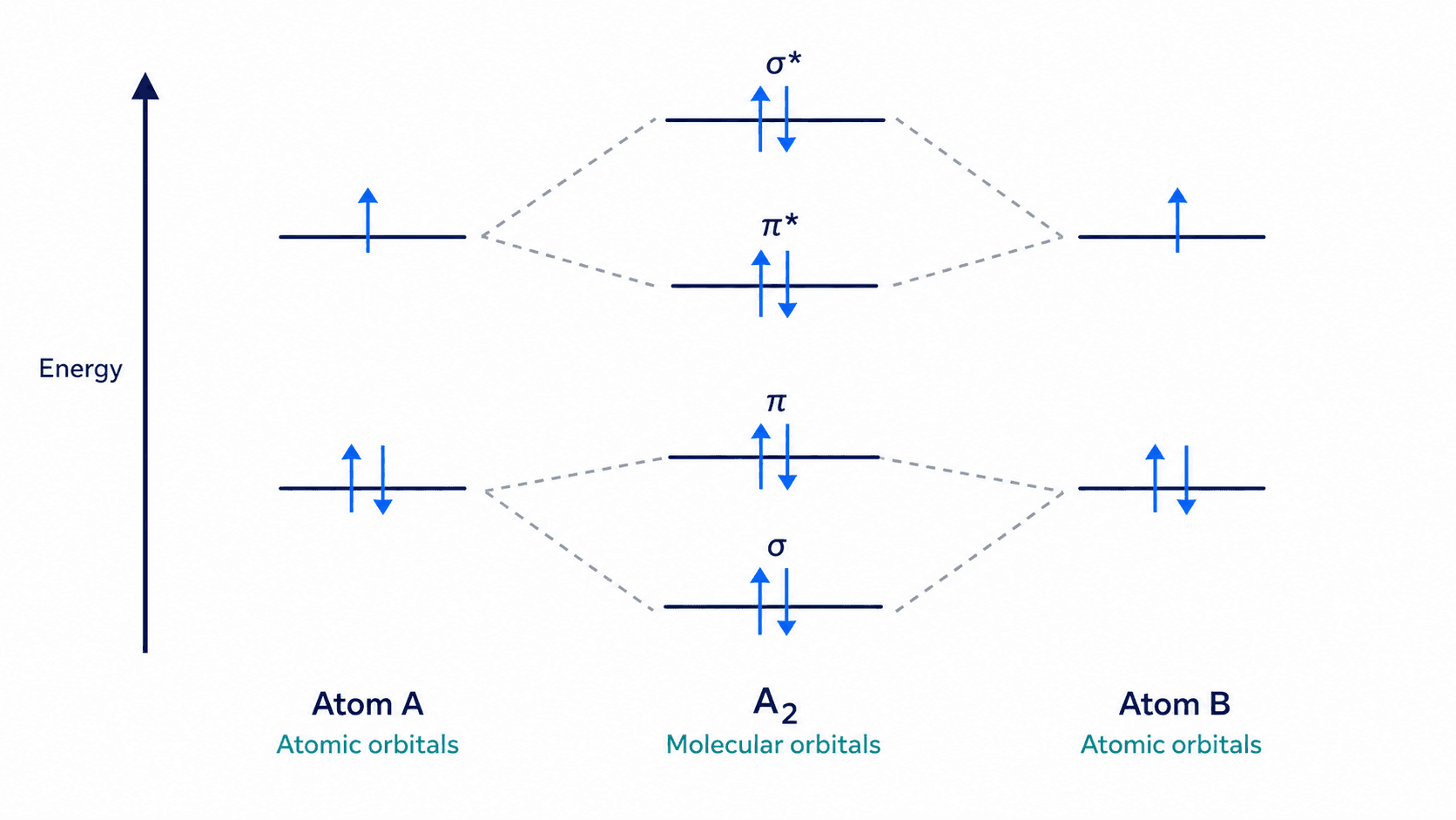
A molecular orbital (MO) diagram looks intimidating because it stacks a lot of information — energy levels, electron filling, and bond order — into one figure. The reliable way to draw one is to build it in a fixed order: place the atomic orbitals on each side, combine them into molecular orbitals in the middle, then fill electrons from the bottom up.
This guide shows you how to draw a molecular orbital diagram from scratch, with worked examples for O₂ and N₂. If you need a clean figure now, the molecular orbital diagram generator can draw a labeled MO diagram from a plain-language description.
Common MO diagram mistakes
Fix these before you fill a single electron:
- Forgetting the s–p mixing swap. For B₂, C₂, and N₂, the σ2p orbital sits above the π2p orbitals. For O₂, F₂, and Ne₂, the order flips and σ2p sits below π2p.
- Filling before pairing correctly. Follow Hund's rule: fill degenerate orbitals (the two π orbitals) singly before pairing them up.
- Ignoring antibonding orbitals in the count. Bond order uses both bonding and antibonding electrons. Skipping the antibonding side gives the wrong answer.
- Mislabeling the asterisk. Antibonding orbitals get a star (σ*, π*). Leaving it off makes the diagram ambiguous.
- Drawing energy levels out of order. Energy increases up the page; place each orbital at the correct relative height.
- Counting core electrons. For second-row diatomics, work with valence electrons only unless the question says otherwise.
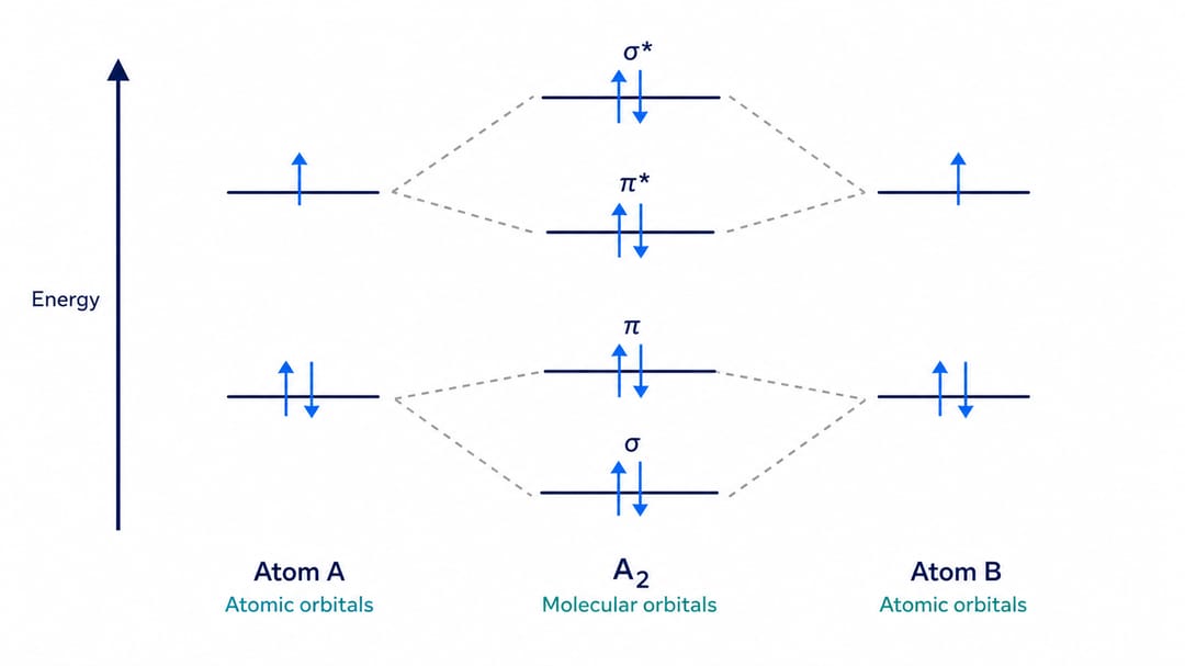
A clear MO diagram places atomic orbitals on the sides, molecular orbitals in the middle, and an energy axis on the left.
Bonding vs. antibonding orbitals
When two atomic orbitals combine, they form two molecular orbitals:
| Orbital type | Energy | Effect on the bond |
|---|---|---|
| Bonding (σ, π) | Lower than the atomic orbitals | Stabilizes the molecule; electrons here strengthen the bond |
| Antibonding (σ, π)** | Higher than the atomic orbitals | Destabilizes the molecule; electrons here weaken the bond |
Electrons prefer the lower-energy bonding orbitals, which is why bonds form at all.
Step-by-step: drawing an MO diagram
- Count valence electrons. Add the valence electrons from both atoms (for ions, adjust for charge).
- Draw the atomic orbitals on the left and right (2s below 2p for second-row elements).
- Add the molecular orbitals in the center: σ2s, σ*2s, then the 2p set.
- Apply the correct 2p order. π2p below σ2p for B₂–N₂; σ2p below π2p for O₂–Ne₂.
- Fill from the bottom up. Lowest energy first, obey Hund's rule and the Pauli principle.
- Calculate bond order: (bonding electrons − antibonding electrons) ÷ 2.
Worked example: N₂
Nitrogen has 5 valence electrons each, so 10 total. Filling in order (σ2s, σ*2s, π2p, π2p, σ2p):
- Bonding electrons: 8 (σ2s + both π2p + σ2p)
- Antibonding electrons: 2 (σ*2s)
- Bond order = (8 − 2) ÷ 2 = 3 — a triple bond, and N₂ is diamagnetic (all paired).
Worked example: O₂
Oxygen has 6 valence electrons each, so 12 total. Here σ2p sits below π2p, and the last two electrons go into the two π*2p orbitals singly:
- Bonding electrons: 8
- Antibonding electrons: 4 (σ2s + two in π2p)
- Bond order = (8 − 4) ÷ 2 = 2 — a double bond, and O₂ is paramagnetic because of the two unpaired electrons. This is the classic result MO theory explains that Lewis structures cannot.
Better prompts for an AI MO diagram
Describe the molecule and the details you need:
- "Draw the MO diagram for O₂ with σ2p below π2p and two unpaired electrons in π2p."*
- "Label bonding and antibonding orbitals with asterisks and show the energy axis."
- "Fill electrons with up/down arrows following Hund's rule."
- "Keep a clean, textbook style with dashed connectors from atomic to molecular orbitals."
The molecular orbital diagram generator turns these into an editable figure, so you can change the molecule or fix the filling order with words instead of redrawing.
Accuracy checklist
Before you submit an MO diagram, confirm:
- Valence electron count is correct.
- The 2p ordering matches the molecule (B₂–N₂ vs. O₂–Ne₂).
- Electrons fill from lowest energy up, following Hund's rule.
- Antibonding orbitals are marked with asterisks.
- Bond order is calculated from bonding minus antibonding electrons.
- Magnetic behavior (paramagnetic vs. diamagnetic) matches the unpaired electrons.
Related guides
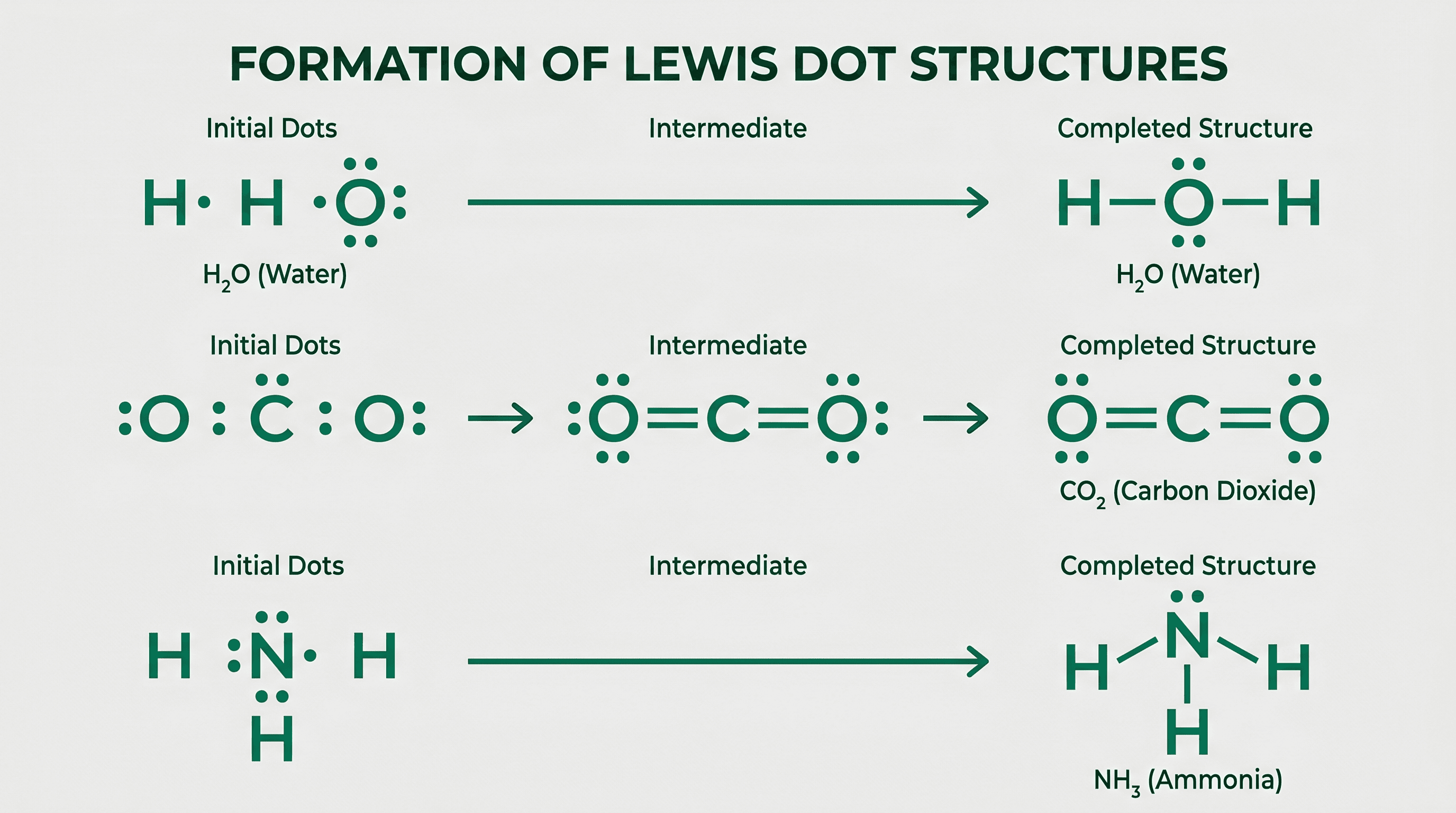
- How to draw Lewis dot structures for the bonding picture MO theory builds on.
- Explore related chemistry tools like the Lewis dot structure generator and chemistry diagram generator.
FAQ
What is the difference between a bonding and an antibonding orbital? A bonding orbital is lower in energy and stabilizes the molecule; an antibonding orbital (marked with an asterisk) is higher in energy and weakens the bond.
Why is O₂ paramagnetic? Its MO diagram places two electrons singly in the two π*2p antibonding orbitals, leaving two unpaired electrons. MO theory predicts this, whereas a simple Lewis structure does not.
How do I calculate bond order? Bond order = (number of bonding electrons − number of antibonding electrons) ÷ 2.
How do I draw an MO diagram quickly? Describe the molecule and electron count to the molecular orbital diagram generator, then refine the labels and filling with words.