Most free body diagram errors happen before the first equation. A normal force gets drawn vertically on an incline, a velocity arrow is mistaken for a force, or gravity is counted twice after it is split into components. Once that diagram is wrong, even perfect algebra produces the wrong result.
This guide gives you a repeatable method for isolating the object, identifying external forces, drawing and labeling vectors, and checking the result before applying Newton's laws. When you already know the forces, the free body diagram maker can turn the description into a clean labeled FBD.
Common free body diagram mistakes
- Drawing forces the object exerts on something else. An FBD shows forces acting on the selected object.
- Adding motion, velocity, or acceleration as forces. These may be annotated separately, but they are not force vectors.
- Calling “centripetal force” an extra force. Centripetal force is the net inward force supplied by real forces such as tension, gravity, friction, or the normal force.
- Assuming the normal force always equals weight. It equals
mgonly in specific cases, such as vertical equilibrium on a horizontal surface with no other vertical forces. - Drawing the normal force straight up on a ramp. It must be perpendicular to the contact surface.
- Drawing friction opposite velocity automatically. Friction opposes relative sliding or the tendency to slide at the contact.
- Including gravity and its components as three separate forces. Draw
mgonce. Components are a coordinate decomposition, not additional forces. - Mixing two objects in one diagram. Draw a separate FBD for each object in a multi-body system.
What is a free body diagram?
A free body diagram (FBD), also called a force diagram, isolates one object and represents every external force acting on it with a labeled vector. The object's detailed shape is usually replaced by a dot or simple box so the force relationships are easier to see.
An FBD is not a picture of the whole physical scene. It is a model used to write equations such as:
ΣFx = max
ΣFy = may
The diagram should contain enough information to build these component equations without adding forces that do not exist.
Forces that commonly appear in an FBD
| Force | Common symbol | Direction |
|---|---|---|
| Weight or gravity | Fg or W = mg | Vertically downward toward Earth's center |
| Normal force | FN or N | Perpendicular to the contact surface |
| Friction | Ff, fs, or fk | Along the surface, opposing relative motion or its tendency |
| Tension | T | Along a taut string, rope, or cable, pulling away from the object |
| Applied force | Fapp | In the stated direction of the push or pull |
| Spring force | Fs = -kx | Opposite the displacement from equilibrium |
| Drag or air resistance | Fd | Opposite the object's velocity relative to the fluid |
| Buoyant force | FB | Upward through the center of buoyancy in a static fluid |
| Electric force | FE = qE | Along or opposite the electric field, depending on charge sign |
Only include a force when another object or field actually exerts it on the selected body.
How to draw a free body diagram step by step
1. Choose one object
State exactly what the diagram represents: “the block,” “the hanging mass,” or “the person in the elevator.” Draw a boundary around that object in the original scene if several bodies are present.
2. Replace the object with a simple shape
Use a dot or box at the center of the FBD. Remove the floor, ramp, rope, and surrounding scenery. Their effects return as forces.
3. List the interactions
Ask two questions:
- What objects touch the selected body?
- What long-range fields act on it?
A block on a rough ramp interacts with Earth (gravity) and the ramp (normal force and possibly friction). A rope adds tension. Nothing else should appear without another interaction.
4. Draw one vector for each external force
Start every arrow at the object. Point it in the force direction and label it immediately. Use longer arrows only when the problem gives magnitudes or the relative sizes are known.
5. Choose axes
For horizontal surfaces, horizontal and vertical axes are usually convenient. On an incline, choose x parallel to the ramp and y perpendicular to it. This minimizes the number of forces that need to be decomposed.
6. Resolve components when useful
On a ramp angled by θ, weight can be resolved into:
mg sin(θ)  parallel to the slope
mg cos(θ)  perpendicular to the slope
Show these as dashed component arrows or in a separate component diagram. Do not count them in addition to the original mg vector when summing forces.
7. Write the net-force equations
Use the diagram to assign signs and build ΣF = ma along each axis. The equations come after the FBD, not before it.
8. Perform a physical check
Ask whether every arrow has a real source, whether its direction is plausible, and whether the net force agrees with the stated acceleration.
Example 1: block on a horizontal surface
A block is pushed right across a rough floor. The four forces are:
- weight
mgdownward, - normal force
Nupward, - applied force
Fappto the right, - kinetic friction
fkto the left.
If there is no vertical acceleration, N - mg = 0. Horizontally, Fapp - fk = ma.
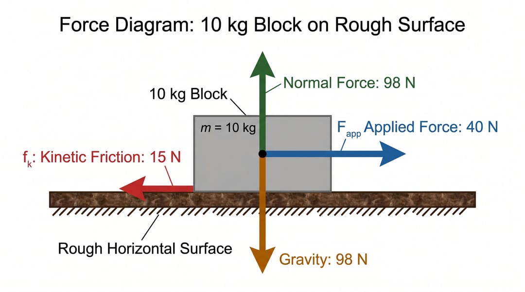
Every vector has an identifiable source: Earth, the floor, or the external push.
Example 2: block on an inclined plane
For a block on a ramp:
mgpoints vertically down,Npoints perpendicular away from the ramp,- friction, when present, lies along the ramp,
- the weight components are
mg sin θdown the ramp andmg cos θinto it.
On a smooth ramp there is no friction. The parallel component produces the acceleration, while the normal force balances the perpendicular component:
ΣFparallel = mg sin(θ) = ma
ΣFperpendicular = N - mg cos(θ) = 0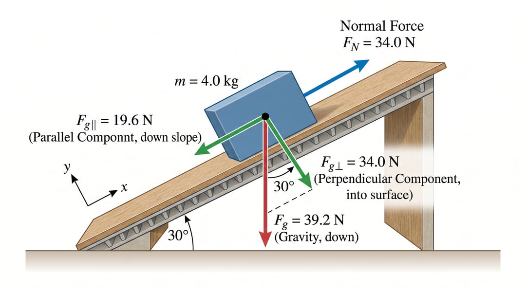
The normal force is perpendicular to the ramp, not vertically upward.
Example 3: person in an accelerating elevator
The person has two forces: weight downward and the elevator floor's normal force upward.
- accelerating upward:
N > mg - moving at constant velocity:
N = mg - accelerating downward:
N < mg
Velocity alone does not determine the force balance. An elevator can move downward while accelerating upward as it slows.
Example 4: projectile at the highest point
With air resistance neglected, a projectile has only its weight acting downward—even at the top of the trajectory. Horizontal velocity is still nonzero, but no horizontal force is required to maintain it.
This is why adding a forward “motion force” is incorrect.
A better prompt for a free body diagram
Poor prompt
Draw forces on a block on a ramp.
Better prompt
Draw a free body diagram for one 4 kg block on a smooth 30° incline. Replace the block with a simple box. Show weight Fg = 39.2 N vertically downward, normal force N = 34.0 N perpendicular away from the ramp, and dashed weight components mg sin 30° = 19.6 N down the slope and mg cos 30° = 34.0 N into the slope. Add axes with +x up the ramp and +y away from it. Do not include friction, velocity, or any extra applied force. Clean physics textbook style, white background.
The better prompt names the object, interaction conditions, forces, directions, values, axes, and exclusions.
Free body diagram checklist
- The diagram isolates one object.
- Every force arrow starts on that object.
- Every force has a real agent or field.
- Weight points vertically downward.
- The normal force is perpendicular to the surface.
- Tension follows the rope and pulls away from the object.
- Friction lies along the surface and opposes relative slipping or its tendency.
- Motion and acceleration are not drawn as forces.
- Components are not double-counted with the original force.
- Vector labels and positive axes are unambiguous.
- The net-force direction is consistent with acceleration.
Make a free body diagram online
Open the free body diagram maker, choose a block, incline, elevator, projectile, or Atwood-machine example, and replace the values with your own. For a broader mechanics figure, the scientific diagram maker can combine the FBD with the physical setup, equations, and explanatory annotations.
SciDraw draws the forces you describe; it does not solve or validate the mechanics problem. Check the completed FBD and equations before using them in homework, teaching, or a lab report.