Free Circuit Diagram Maker
Draw an electrical circuit schematic from plain text
Describe your battery, resistors, switches, bulbs, and LEDs, and AI draws a clean circuit diagram using standard electrical symbols — ready for physics homework, electronics projects, and engineering reports.
Circuit diagram examples
Click any example to load its prompt, or use it as a starting point for your own circuit diagram.
What is a circuit diagram?
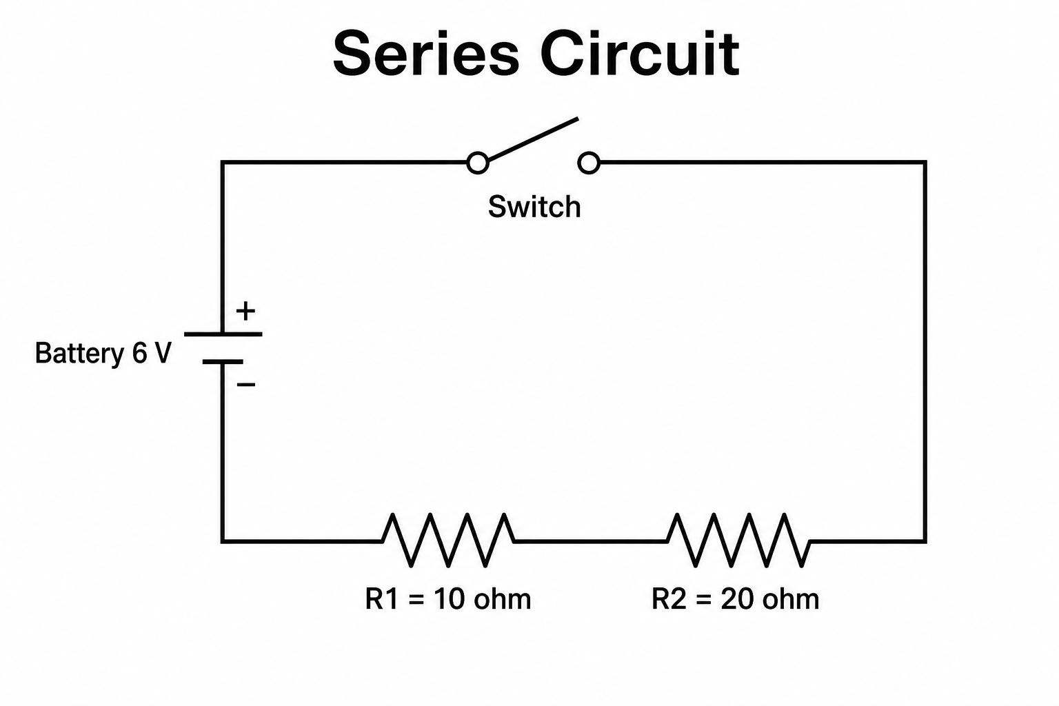
A circuit diagram (also called an electrical or electronic schematic) is a simplified drawing that shows how the parts of a circuit connect, using standard symbols instead of realistic pictures of the components. Each element — battery, resistor, switch, bulb, LED — has its own agreed symbol, and straight wires show how they are joined into a loop. This circuit diagram maker turns a plain-text description into a clean, labeled schematic: you describe the power source, the components and their values, and how they connect, and the AI draws a tidy circuit diagram with the correct symbols, right-angle wiring, and clear labels — no drawing skills or CAD software needed.
Why use a circuit diagram maker
- Circuit diagrams are the universal language for describing electrical and electronic circuits in physics, electronics, and engineering.
- Drawing neat symbols and straight, right-angle wires by hand is fiddly and time-consuming, especially for parallel branches.
- Students learning series and parallel circuits understand them far better from a clearly labeled schematic than from a wall of text.
- Teachers and lab instructors need quick, presentable circuit diagrams for worksheets, slides, and exam questions.
- Changing a value, adding a component, or switching from series to parallel and regenerating is faster than redrawing by hand.
How to draw a circuit diagram
Start with the power source — a cell or battery and its voltage. List the components in the circuit (resistors, switches, bulbs, LEDs, capacitors, meters) with any values, and say how they connect: in series (one loop, one after another) or in parallel (separate branches across the same two points). Add details like the switch position, current direction, or terminal markings if you need them. Generate the circuit diagram, check that the symbols, connections, and labels match what you intended, and refine the description if anything is unclear. Remember this is a drawing tool, so verify the circuit's electrical correctness yourself.
Common circuit symbols
- Battery / cell — the power source; a cell is one pair of long and short lines, and a battery is several cells together.
- Resistor — a rectangle (or zig-zag) that limits current, usually labeled with its resistance in ohms.
- Switch — an open or closed gap in the wire that breaks or completes the circuit.
- Bulb / LED — a lamp symbol or a diode-with-arrows symbol that gives out light when current flows.
- Wires & junctions — straight connecting lines, with a dot marking a junction where wires are electrically joined.
- Ammeter / voltmeter — a circle marked A (in series, measures current) or V (in parallel, measures voltage).
Circuit Diagram Maker FAQ
What is a circuit diagram?
A circuit diagram is a simplified drawing that shows how the components of an electrical or electronic circuit connect, using standard symbols for the battery, resistors, switches, bulbs, and wires. It is also called an electrical schematic or circuit schematic, and it makes the layout and connections of a circuit easy to read at a glance.
How do I make a circuit diagram online?
Describe your circuit in plain words — the power source and its voltage, the components and their values, and how they connect in series or parallel. This online circuit diagram maker then draws a clean schematic with the correct circuit symbols and tidy wiring for you, with no CAD software or drawing skills required.
Can it draw both series and parallel circuits?
Yes. Just say whether the components are in series or in parallel. In a series circuit the parts sit one after another in a single loop, so the same current flows through each. In a parallel circuit the components are on separate branches across the same two points, so each branch gets the full voltage. You can describe either, or a combination of both.
Does it simulate the circuit, and does it use standard symbols?
SciDraw AI uses standard circuit symbols (cell, resistor, switch, lamp, LED, capacitor, ammeter, voltmeter, and so on) to draw a clean schematic. It is a drawing and labeling tool, not a SPICE-style circuit simulator — it does not calculate currents and voltages or guarantee that a circuit is electrically correct, so always check the values and connections yourself.
Is it free?
Each generation uses a small number of credits. New accounts receive free credits, so you can draw a circuit diagram without any subscription.
Can I use it for physics class or a lab report?
Yes. The circuit diagram generator produces clean, labeled schematics that are well suited to physics homework, electronics projects, worksheets, and lab reports. Because it draws rather than simulates, confirm that the circuit is electrically correct before relying on it for a formal assignment.
Explore More Tools
Need other schematics or science figures?
Draw general schematic diagrams, free body diagrams, and more scientific figures with SciDraw AI.